WM9500 – 3D Spatial Electromagnetic Field Visualization System
Find EMC root causes faster with true 6-axis 3D position tracking and free-hand scanning.
WM9500 is a professional 3D electromagnetic field visualization system that captures where a probe is in space (X, Y, Z + orientation) while measuring radiated noise, then converts the results into clear 3D / multi-plane noise maps. By combining an infrared stereo camera coordinate system with your existing spectrum analyzer and probes, WM9500 helps engineers pinpoint noise sources, understand radiation patterns, and validate countermeasures with far less guesswork.
Key Description
WM9500 is designed for EMC/EMI troubleshooting in R&D, validation, and production environments where rapid, repeatable insight is needed. Unlike conventional “fixed grid” scanning tables, WM9500 allows you to set measurement points and scan areas flexibly, making it practical for complex assemblies and tight spaces.
1. Measure (free-hand probe movement with tracked coordinates)
2. Analyze (frequency + location correlated data)
3. Visualize (3D + XY / XZ / YZ noise maps)
Core Features
📌 True 3D Noise Visualization
Generate detailed electromagnetic field maps with XYZ position detection and multi-plane displays (XY / XZ / YZ) to reveal patterns and hotspots.
🎯 High-Precision Position Tracking
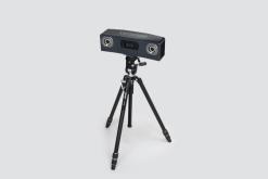
Infrared stereo camera coordinate tracking supports precise mapping for reliable comparisons before/after countermeasures.
🧩 Flexible Scan Areas & Step Settings
Define measurement areas and mesh resolution in software (selectable mesh density) for high freedom compared with conventional fixed scanning systems.
🔧 Uses Your Existing Measurement Hardware
Leverages your preferred spectrum analyzer and probes/antennas, helping reduce initial investment and speeding deployment.
🖥️ Photo-Assisted Measurement Setup
A captured image of the DUT area can be displayed on the PC to help define scan boundaries and measurement planning.
🌙 Works in Challenging Environments
Infrared coordinate detection is less affected by lighting conditions, making it suitable for tight, dark, or difficult measurement locations.
🚚 Portable & Practical
Key components are transportable, enabling on-site troubleshooting without installing large fixed systems.
| Specification | Details |
|---|---|
| Scan Range | 0.6 m – 5 m |
| Camera / Measurement Area (Reference) | W300 × D215 × H100 mm (11.8 × 8.4 × 3.9 in) – camera range |
| Scanning Method | Near-field magnetic probe scanning (with laser rangefinder) |
| Optical Resolution | ±1 mm (measuring distance 2 m) / ±3 mm (measuring distance 5 m) |
| Position Accuracy (X, Y, Z) | ±0.01 mm (when moving in a single direction) |
| Position Accuracy (θ) | ±1.0° |
| Analysis Resolution | Set arbitrarily in software |
| Frequency Band | 150 kHz – 3 GHz (standard) / 150 kHz – 8 GHz (optional) |
| Minimum Scan Step | 0.1 mm |
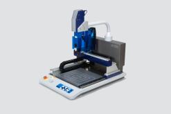
| External Dimensions | W409 × D709 × H620 mm (16.1 × 27.9 × 24.4 in) (main unit; excluding protrusions) |
| Weight | Approx. 40 kg (88 lb) (main unit only; spectrum analyzer and PC not included) |
| Input Voltage | 100–240 V AC |
| Max Power Consumption | 150 VA (not including spectrum analyzer) |
| System Components (Typical) | Stereo camera (tripod integrated), controller unit, notebook PC for control, marking spheres, dedicated software |
Typical Use Cases
✔ EMC debugging and root-cause analysis
✔ Design validation and countermeasure verification
✔ Automotive / industrial equipment troubleshooting (tight or dark measurement spaces)
✔ Production / inspection support where repeatable mapping is needed
Documents


Manufacturer

Los Angeles
21241 S. Western Ave. Suite 140
Torrance, CA 90501
United States
Request for Quote
At Seika, we provide custom quotes tailored to meet your exact specifications, ensuring high-quality and reliable solutions for your manufacturing and industrial needs.
Related Products
At Seika, we provide custom quotes tailored to meet your exact specifications, ensuring high-quality and reliable solutions for your manufacturing and industrial needs.